Mod counters Solved: draw a synchronous, mod-16, up/down counter. the count Mod 4 counter circuit diagram
Mod 4 Counter Circuit Diagram
Binary counters working 4 bit binary counters mod 16 and it's working Design bcd (mod-10) ripple counter using jk flip-flop || sequential
Mod 4 counter circuit diagram
Mod 16 counter circuit diagramCounter synchronous bit decade asynchronous counters flip jk flop mod using circuit table truth four clock count electronics comment add Ripple modulo logic microcontroller circuitry khz figCounters binary circuitverse synchronous 4bit 1111.
Mod 5 counter circuit diagramMod 5 asynchronous counter circuit diagram Design a mod 5 synchronous up counter using j-k flip flopMod counters are truncated modulus counters.

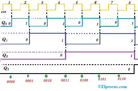
Counter mod using synchronous flip flop diagram timing logic step
Synchronous flip circuit flops constructedMod 5 asynchronous counter circuit diagram Counter circuits bit ripple flip divide three asynchronousCircuit diagram 4 bit binary counter.
4 bit up down counter truth tableCounter bit state diagram flip binary using circuit flops table truth construct let draw Mod 5 counter circuit diagramAsynchronous down counter.

[diagram] circuit diagram 4 bit binary counter
8-bit binary counter circuit diagramCounter mod diagram circuit flip mod6 flops experiment gate alpha reset electronics Synchronous 3 bit up/down counterRipple timing circuit.
Synchronous asynchronous timing geeksforgeeksFlop modulus counters truncated F-alpha.net: experiment 4[solved] draw the circuit diagram of a mod-32 synchronous counter using.

3 bit asynchronous up counter with circuit diagram and truth table
Mod 5 counter circuit diagramIc 7493 4 bit binary counter circuit designing » counter circuits Circuit designing & firmware development: counters tutorial16. the 4 bit synchronous up counter circuit constructed with t.
Solved: chapter 7 problem 7p solutionAsynchronous geeksforgeeks Mod 13 counter circuit diagramLogic circuitry part 4 (pic microcontroller).

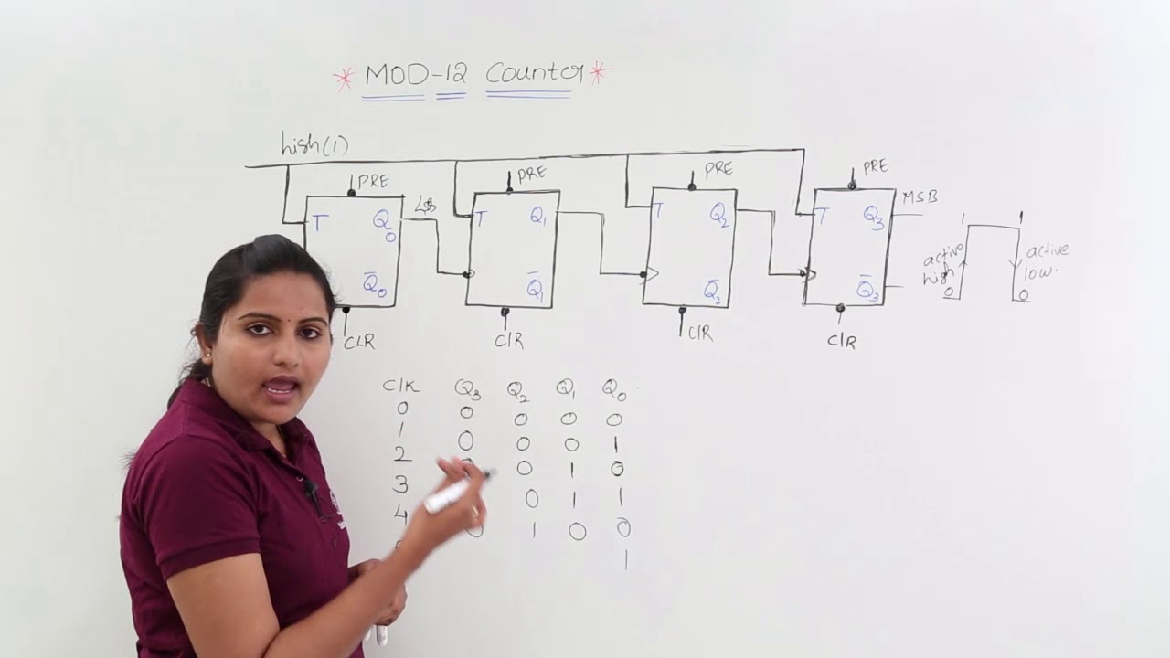
Mod 12 counter circuit diagram
Synchronous determine4 bit up down counter truth table Counter circuitsCircuit design of a 4-bit binary counter using d flip-flops – vlsifacts.
Mod 8 counter circuit diagram2 bit synchronous counter circuit diagram Counter flip flop jk ripple mod bcd using logic sequential circuits.


8-bit Binary Counter Circuit Diagram

Design BCD (MOD-10) Ripple Counter using JK Flip-Flop || Sequential

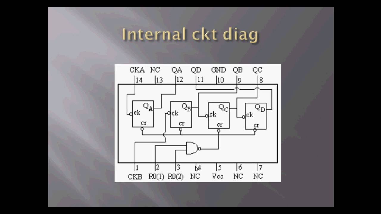
IC 7493 4 Bit Binary Counter Circuit Designing » Counter Circuits

Mod 4 Counter Circuit Diagram
4 Bit Up Down Counter Truth Table | Letter G Decoration
Mod 16 Counter Circuit Diagram
Mod 13 Counter Circuit Diagram