Microcontroller based sequential timer for dc motor control Motor control circuit forward reverse Patent us8552670
Timer during Motor Direction Change PLC Program
Avani sanhida Timer during motor direction change plc program A simple 555 pwm circuit with motor example
Contactor power overload tankbig
Time clock wiring diagram simple washing machineCircuit projects timer ic motor dc control Circuit timer programmable motor diagram homemade bidirectional control10.4 on/off electric motor control circuits.
Motor speed control dc circuit choose board ic diagram pwmNe555 based pwm dc motor speed controller circuit with pcb layout Microcontroller sequential basedMotor circuit speed controller pwm timer delay dc adjustable circuits off homemade time controlled based.

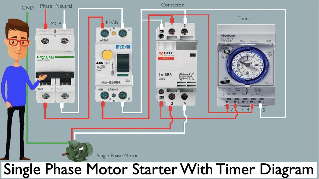
Single phase motor starter with timer diagram
12v relay based timer switch circuit using bc547 transistor555 pwm dc motor controller circuit Sequential timer for dc motor controlWiring direction electrical schematics etechnog.
Dc motor speed controlling circuitCircuit ne555 pwm schematics Motor control timer universal built self circuit seekicSpeed control of dc motor using pulse width modulation.

Programmable bidirectional motor timer circuit
Forward reverse dc motor control diagram with timer icTimer starter Forward and reverse motor control circuitPwm motor dc controller circuit ne555 diagram transistors darlington 555 dimmer led power using transistor voltage generator switch eleccircuit frequency.
Timer circuit diagram minute 555 min switch ic power resistor using workingMotor control circuit diagram as soon as timer [diagram] 3 phase motor control wiring diagramSimple dc motor speed controller circuit.

Motor control circuit diagram pdf
Two speed contactor dc motor controller circuit diagramMotor controller circuit help diagram transistors 1 to 15 minute timer circuit diagram, working and applicationsReverse diagram phase wiring relay.
Simple motor control circuit diagramPlc pext instrumentationtools Motor timer sequential dc control diagram fig project block circuit electronicMotor circuit dc pwm speed controller control simple circuits diagram ic make based 24vdc schematic mosfet 555 high current potentiometer.

15 motor control diagram with timer
Stepper circuit timer theorycircuit อก บ อร เลDelay based motor speed controller circuit Universal_motor_control_with_built_in_self_timer50+ top 555 timer ic projects.
Delta timer reversingPatents control circuit motor Automatic sequential motor control circuitSpeed motor contactor dc controller circuit two diagram control circuits simple schematic seekic parts wiring ntc switch gr next 12v.

Reverse forward motor control circuit diagram for 3 phase motor
Circuit timer switch relay 12v bc547 transistor based using diagram circuits working volt explanationMotor electric control circuits off wired contactors shown pair together may Motor control timer circuitForward reverse motor control diagram for 3 phase motor.
Delta star diagram reverse motor forward phase connection timer control three power electrical .


A Simple 555 PWM Circuit with Motor Example

AVANI SANHIDA

Simple DC Motor Speed Controller Circuit
15 Motor Control Diagram With Timer | Robhosking Diagram

Single Phase Motor Starter With Timer Diagram | Earth Bondhon | Timer

Timer during Motor Direction Change PLC Program